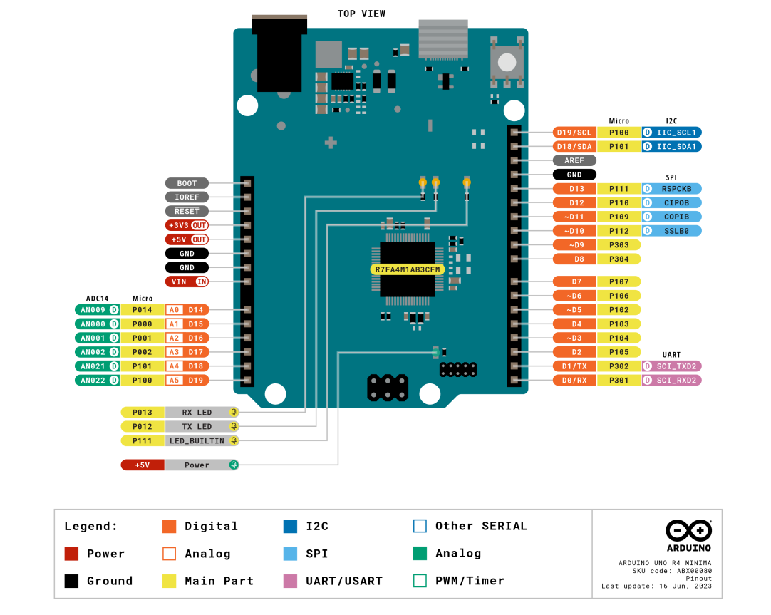
Arduino UNO R4 Minima Pinouts
Op deze pagina vindt je de pinouts voor de Arduino UNO R4 Minima.
Analoge pins:
| Pin | Function | Type | Description |
|---|---|---|---|
| 1 | BOOT | MD | Mode Selection |
| 2 | IOREF | IOREF | Reference for digital logic V - connected to 5 V |
| 3 | Reset | Reset | Reset |
| 4 | +3V3 Power | +3V3 Power | Rail |
| 5 | +5V Power | +5V Power | Rail |
| 6 | GND Power | Power | Ground |
| 7 | GND Power | Power | Ground |
| 8 | VIN Power | Power | Voltage Input |
| 9 | A0 Analog | Analog | Analog input 0 / DAC |
| 10 | A1 Analog | Analog | Analog input 1 / OPAMP+ |
| 11 | A2 Analog | Analog | Analog input 2 / OPAMP- |
| 12 | A3 Analog | Analog | Analog input 3 / OPAMPOut |
| 13 | A4 Analog | Analog | Analog input 4 / I²C Serial Data (SDA) |
| 14 | A5 Analog | Analog | Analog input 5 / I²C Serial Clock (SCL) |
Digitale pins:
| Pin | Function | Type | Description |
|---|---|---|---|
| 1 | SCL | Digital | I²C Serial Clock (SCL) |
| 2 | SDA | Digital | I²C Serial Data (SDA) |
| 3 | AREF | Digital | Analog Reference Voltage |
| 4 | GND | Power | Ground |
| 5 | D13/SCK | Digital | GPIO 13 / SPI Clock |
| 6 | D12/CIPO | Digital | GPIO 12 / SPI Controller In Peripheral Out |
| 7 | D11/COPI | Digital | GPIO 11 (PWM) / SPI Controller Out Peripheral In |
| 8 | D10/CS | Digital | GPIO 10 (PWM) / SPI Chip Select |
| 9 | D9 | Digital | GPIO 9 (PWM~) |
| 10 | D8 | Digital | GPIO 8 |
| 11 | D7 | Digital | GPIO 7 |
| 12 | D6 | Digital | GPIO 6 (PWM~) |
| 13 | D5/CANRX0 | Digital | GPIO 5 (PWM~) / CAN Transmitter (TX) |
| 14 | D4/CANTX0 | Digital | GPIO 4 / CAN Receiver (RX) |
| 15 | D3 | Digital | GPIO 3 (PWM~) / Interrupt Pin |
| 16 | D2 | Digital | GPIO 2 / Interrupt Pin |
| 17 | D1/TX0 | Digital | GPIO 1 / Serial 0 Transmitter (TX) |
| 18 | D0/TX0 | Digital | GPIO 0 / Serial 0 Receiver (RX) |
ICSP pins:
| Pin | Function | Type | Description |
|---|---|---|---|
| 1 | CIPO | Internal | Controller In Peripheral Out |
| 2 | +5V | Internal | Power Supply of 5 V |
| 3 | SCK | Internal | Serial Clock |
| 4 | COPI | Internal | Controller Out Peripheral In |
| 5 | RESET | Internal | Reset |
| 6 | GND | Internal | Ground |
SWD/JTAG pins:
| Pin | Function | Type | Description |
|---|---|---|---|
| 1 | +5V | Internal | Power Supply of 5 V |
| 2 | SWDIO | Internal | Data I/O pin |
| 3 | GND | Internal | Ground |
| 4 | SWCLK | Internal | Clock Pin |
| 5 | GND | Internal | Ground |
| 6 | NC | Internal | Not connected |
| 7 | RX | Internal | Serial Receiver |
| 8 | TX | Internal | Serial Transmitter |
| 9 | GND | Internal | Ground |
| 10 | NC | Internal | Not connected |


