Motor driver module L298N Dual H-Bridge with current sensing
Product information:
The L298N Dual H-Bridge Motor Driver is a motor driver board that can be used to drive two robot motors. It uses the popular L298N Dual H-Bridge Motor Driver chip and is powerful enough to drive motors from 5-35 volts with up to 2 amps per channel. The flexible digital input controls ensure that each motor is completely independent with full control over speed direction and braking action.
This board provides a convenient 5V regulator that can be used to power other circuits, such as your robotics microcontroller. The modular design can be easily adapted to a wide range of robotics controllers, including the popular Arduino family.
See how to use it with an Arduino here:
https://create.arduino.cc/projecthub/ryanchan/how-to-use-the-l298n-motor-driver-b124c5
Features:
- Popular L298N Dual H-Bridge Motor Driver chip
- Controls motors from 5-35V up to 2A per channel
- Provides 4 LEDs to indicate the status of the control logic
- Independent direction, speed and braking for each motor
- Screw terminals for easy connection to motors and power
- Features a heavy-duty heatsink for maximum performance
- Easy to pair with most robot controllers
- Supports current detection
- Handy power LED
- With header pins for current sensing (leave jumpers in place if you don't use the pins).
Specifications:
- Input voltage: 5-35V
- Output current: 2A per channel
- Control logic: standard 5V TTL
- Power consumption: 36ma for logic
- Dimensions: 55mm x 60mm x 30mm
- Weight: 33 grams
Screw terminal pin connections| Pin | Colour | Name | Description |
|---|
| 1 | Green | Engine A - | Output to Motor A (-) |
| 2 | Green | Engine A+ | Output to Motor A (+) |
| 3 | Blue | VMS | Input 4-35V motor power connection (+) |
| 4 | Blue | GND | Earth(-) |
| 5 | Blue | 5V | 5V regulated voltage (+) |
| 6 | Green | Engine B - | Output to Motor B (-) |
| 7 | Green | Engine B+ | Output to Motor B (+) |
Header pin connections| Pin | Name | Description |
|---|
| 1 | ENA | Input to enable Motor A |
| 2 | IN1 | Input to control Motor A |
| 3 | IN2 | Input to control Motor A |
| 4 | ENB | Input to enable Motor B |
| 5 | IN3 | Input to control Motor B |
| 6 | IN4 | Input to control Motor B |
Jumpers| Name | Description |
|---|
| 5V_EN | Enable the onboard 5V voltage regulator |
| U1 | Enable Motor A input pin IN2 pull-up resistor (10K) |
| U2 | Enable Motor A input pin IN2 pull-up resistor (10K) |
| U3 | Enable Motor B input pin IN3 pull-up resistor (10K) |
| U4 | Enable Motor B input pin IN4 pull-up resistor (10K) |
| CSA | Ties the Motor A current sense to ground |
| CSB | Ties the Motor B current sense to ground |


 Buck converter Step Up/Down DC-DC Uin:5V-32V Uout:1.25-35V 4.0A XL6009
3,95
Buck converter Step Up/Down DC-DC Uin:5V-32V Uout:1.25-35V 4.0A XL6009
3,95
 Microswitch push button (make contact) 6x6x1mm
0,35
Microswitch push button (make contact) 6x6x1mm
0,35
 ESP32 WROOM Development board WiFi/Bluetooth USB-C CH340
10,95
ESP32 WROOM Development board WiFi/Bluetooth USB-C CH340
10,95
 Breadboard jumper cables Dupont 30cm female/female 40PCS
2,25
Breadboard jumper cables Dupont 30cm female/female 40PCS
2,25
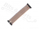 Breadboard jumper cables Dupont 30cm male/male 40PCS
2,25
Breadboard jumper cables Dupont 30cm male/male 40PCS
2,25
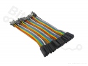 Breadboard jumper cables Dupont 10cm female/male 40PCS
1,40
Breadboard jumper cables Dupont 10cm female/male 40PCS
1,40
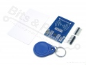 RFID RC522 Controller/Scanner Set 13.56MHz
4,65
RFID RC522 Controller/Scanner Set 13.56MHz
4,65
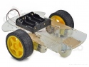 Smart Car Chassis 2WD with 2 motors
12,95
Smart Car Chassis 2WD with 2 motors
12,95
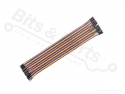 Breadboard jumper cables Dupont 30cm female/male 40PCS
2,25
Breadboard jumper cables Dupont 30cm female/male 40PCS
2,25


 Shipping costs Netherlands




 >
>
